Connection Group Box

Contents
In this group box you can set up the connection to the mount via a COM port, or if you have a GTOCP4/5, also via Ethernet or WiFi.
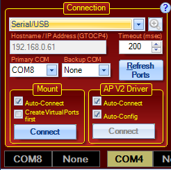
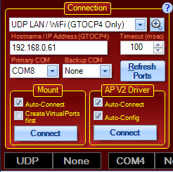
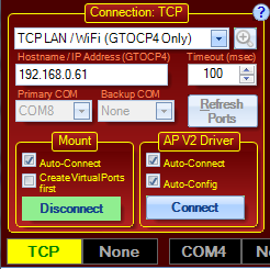
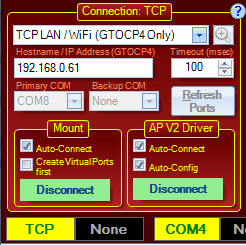
Below are some images showing various states of configuration and connection:
Using GTOCP4/5 with Ethernet Those of you with the GTOCP4/5 Servo Control Box now have the option of connecting directly with Ethernet or WiFi. Ethernet connections can either be direct peer-to-peer connections (cable direct from the computer to the GTOCP4/5) or they can be through a local area network (LAN). In a similar manner, the GTOCP4/5 can have its WiFi configured as an Access Point for direct connection from a WiFi enabled PC, or it can join your established WiFi network in Station Mode. See IP connections below. |
Serial/USB: To put APCC in serial port mode. The Hostname/IP Address field will become disabled when this radio button is selected. The Primary and Backup COM Port drop down list boxes will become available.
Note on USB: The USB connection on the GTOCP4/5 is treated the same as a normal serial port as far as APCC or the AP V2 driver is concerned. If you are connecting with USB, simply follow the instructions for COM ports below as if it were a serial port. Please note that you MUST first install the FTDI Driver onto your computer for USB to operate properly. he latest driver can be found at http://www.ftdichip.com/drivers/vcp.htm . Note also that the FTDI USB to serial devices are all uniquely serialized. Each one will be assigned its own COM port that will be remembered through power-cycles.
Ethernet or WiFi (GTOCP4/5 Only): To put APCC into IP mode for Ethernet or WiFi connection, simply select this radio button. The two COM Port's drop-down boxes will become inactive, and the Hostname/IP Address box will become active. The Hostname/IP Address box is not a drop-down box, but requires the entry of either the appropriate Hostname or IP address. It is always preferable to use the true IP address, but it is generally easier to use the Hostname
Connection Types:
oSerial/USB: To put APCC in serial port mode. The Hostname/IP Address field will become disabled when this is selected. The Primary and Backup COM Port drop down list boxes will become available.
oUDP LAN / WiFi (GTOCP4/5 Only): UDP is a lightweight connectionless protocol that usually will be the best choice when connected to the CP4/5 with a reliable hard-wired connection. It can also be used for WiFi connections but the UDP protocol does not guarantee delivery of packets. APCC tries to resend a command one time if it gets no response, then it will report an error. To check the error count click the "Comm Events" button in APCC' status bar. You can only click this button if there are errors.
Note that when this option is selected the two COM Port's drop-down boxes will become inactive, and the Hostname/IP Address box will become active. The Hostname/IP Address box is not a drop-down box, but requires the entry of either the appropriate Hostname or IP address. It is always preferable to use the true IP address, but it is generally easier to use the Hostname. Clicking the Find GTOCP4/5 (magnifying glass) button will broadcast a request out to your local network. Any GTOCP4/5 that gets the broadcast should and respond.
oTCP LAN / WiFi (GTOCP4/5 Only): TCP is a more robust connection-oriented protocol. It has considerably more overhead than UDP both in system and network resources but it is generally more reliable than UDP. It can be used for both wired and WiFi connections. In general it is better to use the lighter weight UDP protocol unless you start to see a considerable number of errors.
Note that when this option is selected the two COM Port's drop-down boxes will become inactive, and the Hostname/IP Address box will become active. The Hostname/IP Address box is not a drop-down box, but requires the entry of either the appropriate Hostname or IP address. It is always preferable to use the true IP address, but it is generally easier to use the Hostname. Clicking the Find GTOCP4/5 (magnifying glass) button will broadcast a request out to your local network. Any GTOCP4/5 that gets the broadcast should and respond.
Note that the cabled Ethernet Hostname and the WiFi Hostname will be different. In general, unless you have changed them the names will all end in the numeric portion of the GTOCP4/5 serial number without the leading zeros if there are any. For example, the control box with serial number: CP4-0456 would have a cabled Ethernet Hostname of: GTOCP4_456. The WiFi Hostname would be GTO_WIFI_456.
IP addresses can be obtained easily from the GTOCP4/5's main web page. Use the handy ASCOM utility to find the relevant information and open the GTOCP4/5's internal web page. Note that network-based IP addresses are subject to changes, whereas the peer-to-peer and access point IP addresses remain unchanged unless you change them.
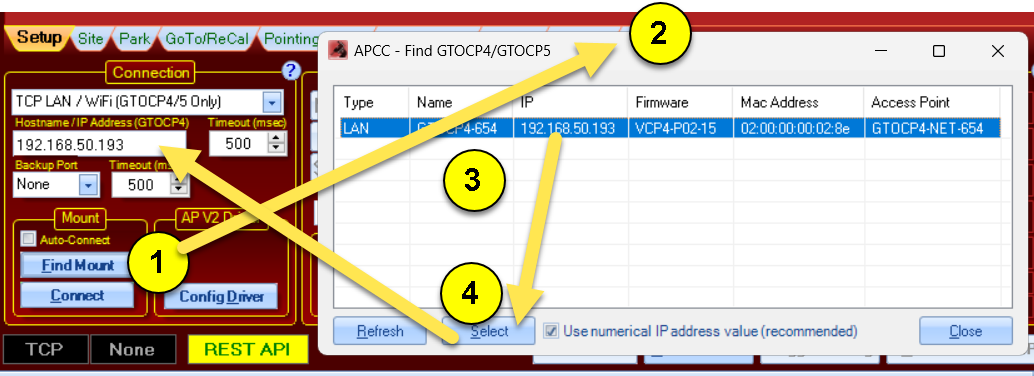
Find GTOCP4/5 button: Clicking the button with a magnifying glass will open a new window and send out a broadcast to find a GTOCP4/5 on the LAN (or WiFi).
Use the following steps as indicated in the picture above:
1) Click the magnifier
2) The Find GTOCP4/5 window will open and report and GTOCP4/5's that respond.
3) Clicking the GTOCP4/5 that you want to connect to will activate the Select button.
4) Clicking the Select button will copy the IP address (if Use IP Address is checked) or the CP4/5's defined name.
Note on USB: The USB connection on the GTOCP4/5 is treated the same as a normal serial port as far as APCC or the AP V2 driver is concerned. If you are connecting with USB, simply follow the instructions for COM ports below as if it were a serial port. Please note that you MUST first install the FTDI Driver onto your computer for USB to operate properly. he latest driver can be found at http://www.ftdichip.com/drivers/vcp.htm . Note also that the FTDI USB to serial devices are all uniquely serialized. Each one will be assigned its own COM port that will be remembered through power-cycles.
Primary COM Port: The list of serial ports that were detected on the computer will be displayed in this drop down list box. Select the default COM port that APCC will use when the Connect to Port button is pressed.
In order to complete your configuration you will need to set up at least one virtual COM port through which the ASCOM driver can communicate to APCC and the mount. See Setting up your primary Virtual Port for more details. Additional information can be found in the Virtual Ports Tab section.
Note for GTOCP3 users: Be sure that your serial cable is connected to the top RS-232 port on the GTOCP3 control box.
Note for GTOAE users: For 1600GTO and 1100GTO owners with the optional Absolute Encoders (and the GTOAE box), there are two options. If you will NOT be using your keypad, use the port that connects through the Keypad receptacle of the GTOCP3. If you wish to have the keypad available for use, then connect APCC directly to the GTOAE box. If you find at some point during your session that you need to use the APAE Utility, simply disconnect APCC by clicking the button as described below. Use the APAE Utility, and when you are finished, close it down and then reconnect with APCC.
GTOCP4/5 users: You do not need to show any preference between the top, bottom and USB ports. All should perform equally well. Since the AE functions are internal to the GTOCP4/5, there are no issues with using the APAE Utility along with APCC.
Backup COM Port: If you choose to, you can select a secondary COM port for APCC to try if the primary COM port has a problem for any reason. To use this feature you will need to use both ports on the control box and will need a second USB/serial port converter. This adds an extra layer of reliability in case the primary USB/serial port converter fails. The backup port will be the bottom COM port of the GTOCP3 control box. Ideally, this should be a physically separate serial port from the primary port. If you simply use another port on a single multi-port USB to serial converter, and the converter or USB connection fails, you will lose both ports and gain nothing. If you use a second USB to serial converter that is attached to a different USB port on the computer, you are much more likely to survive a COMs problem.
Timeout: Here you can set the timeout in milliseconds for responses from the mount. In Ethernet or WiFi mode, the ideal timeout can be quite variable depending on the rest of your system. We suggest starting out at 50 ms for cabled Ethernet connections, and try 100 - 200 ms for WiFi networks. For COM ports - whether serial or USB, usually 100 or 200 ms is good enough. However, sometimes it may be necessary to increase this value to 300, 400 or even 500 ms. (Note the difference between this recommended setting and the longer recommendation for the AP V2 ASCOM Driver when it is used through APCC's Virtual Ports.)
Refresh Ports Button: As its name implies, clicking this button will refresh the list of COM ports available on the PC. The updated list will then appear in the COM port selection drop-downs.
Mount Sub-Group Box: This group-box has two check-boxes for mount connection options as well as the Connect/Disconnect Button:
Auto-Connect - When this is checked, APCC will attempt to connect to the mount as a part of its start-up sequence. If you have this box checked, you will want to have an overall start-up procedure that powers the mount ON before starting APCC. This is common and is recommended in permanent and remote systems. Once connected, APCC will proceed through the initialization procedure you have previously defined. Also if the first virtual port is set to "None" a com port will be automatically assigned to it.
Create Virtual Ports first - When this is checked, your defined virtual ports are all created upon APCC start-up, whether or not APCC is connecting to the mount.
Connect/Disconnect Button - Click to connect. The button will turn green to indicate successful connection. Click to disconnect.
AP V2 Driver Sub-Group Box: This group-box has two check-boxes for mount connection options as well as the Connect/Disconnect Button: To connect APCC to your mount, press this button. Note that if an ASCOM application invokes the driver and the driver cannot connect to APCC on its virtual port then the driver will try to start a new instance of APCC and wait until the connection has been established. As stated earlier, it is generally preferable to start APCC and have it create its first virtual port and connect to the driver before asking an ASCOM client program to connect.
Auto-Connect - Once APCC has started, it will automatically create the first virtual port (even if the previously discussed check box is un-checked) and create an instance of the AP V2 Driver. This also is common and is recommended in permanent and remote systems.
Auto-Config - When this is checked, APCC will automatically configure the relevant sections of the AP V2 Driver's settings in order for the driver to connect properly. The "Auto-Configure" driver option will change these APCC/driver settings:
1) Enable the "APCC Virtual Port" option in the settings window.
2) Define the first virtual port in APCC if not defined.
3) Set the driver's COM port to match the first APCC virtual port.
4) Set the driver's COM Port Timeout value (mSecs) to 1000 msecs if it is less than that (won't change it if it is already 1000 or greater).
5) Set the driver's COM Port retry count to 0.
6) Turn off the driver's (internal) Convert Alt/Az to RA/Dec option.
7) Turn off the driver's autocalibrate N/S/E/W on first slew option.
8) Turn on "Allow Connect if Mount not present" in driver.
9) Set the Connect Timeout (in secs) to be the APCC auto-initialize timeout value (in secs) + 10 seconds.
IMPORTANT: Please uncheck Auto-Config If you plan to start APCC by first connecting an ASCOM client to the AP V2 ASCOM driver before APCC has been started. The driver will attempt to start APCC but since the driver is already active it cannot be reconfigured by APCC. A warning message may come up indicating this but you can ignore it. The message will disappear after a few seconds. Note that for the driver to start APCC the APCC Virtual Port check box must be enabled in the AP V2 ASCOM Drivers setup window.
Connect/Disconnect Button - Connects to or disconnects from the driver. When connecting to the driver APCC will always check that the driver's COM port matches APCC's first virtual COM port. If it doesn't match APCC will automatically try to change the driver's COM port to match APCC's first virtual port. APCC also will enable the driver's "APCC Virtual Port" setting if it was not enabled. This provides extra command/reply checking of commands between APCC and the driver, including embedded sequence numbers in each command.