COM Port Details

Contents
IMPORTANT: The two RS-232 serial ports on the GTOCP3 control box are NOT identical. There are two universal asynchronous receiver/transmitters, or UART devices that control serial communication in the GTOCP3.
• Top RS-232 and Keypad serial ports: The primary UART is built into the EPROM chip that is the microcontroller “brains” of your mount. It is in fact a dual UART and it serves both the top RS232 port and the Keypad receptacle. This is why all keypad firmware updates must be done through the top port of the GTOCP3.
• Lower RS-232 serial port: The second UART is found on a field programmable gate array (FPGA chip) in the control box. While this UART is suitable for many applications, it does have certain limitation vis-à-vis the primary UART. Of particular concern to users of high demand (or high traffic) software, including the ASCOM V2 driver, is the lower over-sampling ratio in the second UART. This makes the lower RS232 port more susceptible to framing errors due to noise, differences in the number of start bits, baud rate mis-matches, etc.
The issue with the lower RS-232 port is not really a problem with either the port’s UART or the ASCOM V2 Driver, both of which work as they should. It is instead related to the PC hardware, and possibly how the operating system or system services are configuring it. The port selection is, however, the only aspect of this that we as end users have any control over.
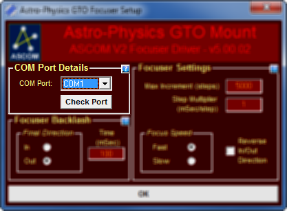
COM Port: Com Port to use. This port should be the same as what is set for the telescope. Additional COM port details can be setup in the Telescope Setup Dialog. Check Port: click this to test if the mount is connected. The mount must be powered up for the driver to receive a response. It does not need to be initialized yet. |
|